
Required equipment:
- Consibio Logger in Rugged Case
- Vegapuls C21 radar sensor
- Crossbeam (mounting bar)
- Cable hanger
- Measuring stick (for manual water level measurement)
Overview
2. Slide the cable hanger onto the crossbeam
5. Position cable hanger in center
6. Insert sensor cable in cable hanger
8. Manual Water Level Measurement
9. Calibrate Water Level Measurement
Step-by-step
0. Pre-Deployment Setup
-
Charge the equipment - Ensure all equipment is fully functional and that the logger batteries are charged to at least 90% before deployment.
- Configure the Logger
-
Log in to Consibio Cloud.
-
Locate your Project and navigate to the “Devices” tab.
-
Select the relevant logger device.
-
Set the Transmission Interval to 3 minutes and the Measurement Interval to 30 seconds, to ensure timely and consistent data collection during deployment.
- If the logger is currently in a sleep cycle, press the physical wake-up button and hold it for >15s to force a check-in. The LEDs will "spin" when the device goes online.
-
1. Open crossbeam
Open up the crossbeam by unscrewing the wingnut:
2. Slide the cable hanger onto the crossbeam
3. Mount Logger
Slide the Consibio Logger in a rugged case onto the crossbeam:
4. Assemble and adjust crossbeam
Adjust the width of the crossbeam to the width of the manhole and fasten the wingnut. The crossbeam should be as wide as possible to ensure that it will not fall off and into the manhole.
5. Position cable hanger in center
Align the crossbeam and cable hanger so they are centered over the channel/invert.
6. Insert sensor cable in cable hanger
Determine where to install the sensor:
-
High Mounting: Install the sensor near the top of the manhole (if depth is <50 ft / 15 m).
Allows monitoring of normal level/flow conditions in the invert while also capturing rising water levels during surcharge events — all the way to the top of the manhole. -
Low Mounting: Install the sensor 3–4 ft (1–1.2 m) above the highest expected daily level.
Provides higher accuracy with less risk of signal disturbance.
Install the sensor cable in the cable hanger. Use the two sliders to grip the cable and hold it in place:
.
.
7. Lock sensor cable
Lock the cable in the cable hanger in place with a cable tie to ensure that it doesn't move:
.
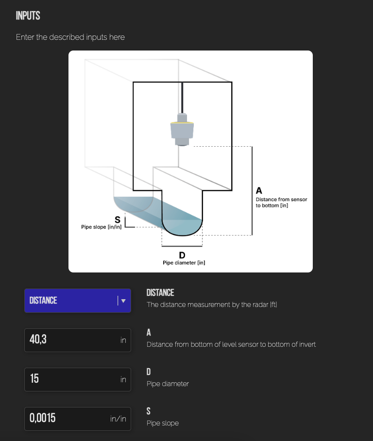
8. Retrieve installation parameters to display level and flow
You need three different measures to properly calculate the flow from the sensor readings:
- A: The installation height, ie. the distance from the bottom of the sensor to the bottom of the invert (in inches)
- D: The pipe diameter (in inches).
- S: The slope of the pipe (inch / inch)
The diameter (D) and the slope (S) can usually be looked up in the pipeline documentation.
The installation height (A) has to be measured manually after installing the sensor. It is very important, that this measure is as accurate as possible, because it will directly affect the accuracy of the flow.
There are two ways to get an accurate installation height:
-
Most practical: Measure the current water level with a long rod
After the device has been deployed, and you have ensured that it is transmitting while inside the manhole, put a long rod into the bottom of the manhole and pull it back up. Measure how far the rod was wetted and note down the exact time of the measurement.
Then, go to Consibio Cloud and check the distance output of the sensor (ie. the distance from the sensor to the water surface).
The installation height (A) is the sum of these two measures:
A = water level [in] + distance [in] (at the same time of the water level measurement)
You are also more than welcome to send the measured water level and the time of measurement to our support team, and they will help set the rest up:
support@consibio.com
-
Less practical: Direct measurement
If there is not much water in the pipe, and you are doing a confined space entry in the manhole, you can measure the distance between the bottom of the invert and the bottom of the sensor directly with a ruler or measuring tape.
When you have these measures, go to Virtual Sensors and enter them in the Virtual Sensor for flow calculation:
9. Verify Level and Flow Data
Check the dashboard to confirm that level (and optional flow) readings look correct:
10. Place the Manhole Cover Back in Position & Verify Signal
Put the manhole cover back on. Wait 4–8 minutes, then verify that the logger successfully completes another check-in under the Devices tab.
If the logger is not able to transmit through the cover use the external antenna.
11. Adjust Transmission and Measurement Intervals
To preserve battery life, update the logger settings:
-
Transmission Interval: Set to a more reasonable value (e.g., 1-12 hours)
-
Measurement Interval: Set based on your monitoring needs (e.g., 5–15 minutes for long-term deployments)
12. Installation Complete
Congratulations — your installation is now complete!
Sit back and enjoy the data coming in.